Nonlinear Sectional Analysis of Reinforced Concrete (NSARC)
1. Input Parameters:
| B. Concrete Cross-Section: | |
| I. Length of wall, Lw (mm) : | |
| II. Thickness of the wall, tw (mm) : | |
| Reinforcement Ratio (Pv > 0.0025) or Spacing (S) in mm: |
| No. of layer of reinforcements: |
| Depth from Bottom (mm) | Area, Ast (mm2) | |
| 1 | ||
| 2 | ||
| 3 | ||
| 4 | ||
| 5 | ||
| 6 | ||
| 7 | ||
| 8 | ||
| 9 | ||
| 10 | ||
| 11 | ||
| 12 | ||
| 13 | ||
| 14 | ||
| 15 | ||
| 16 | ||
| 17 | ||
| 18 | ||
| 19 | ||
| 20 | ||
| 21 | ||
| 22 | ||
| 23 | ||
| 24 | ||
| 25 | ||
| 26 | ||
| 27 | ||
| 28 | ||
| 29 | ||
| 30 | ||
| 31 | ||
| 32 | ||
| 33 | ||
| 34 | ||
| 35 | ||
| 36 | ||
| 37 | ||
| 38 | ||
| 39 | ||
| 40 |
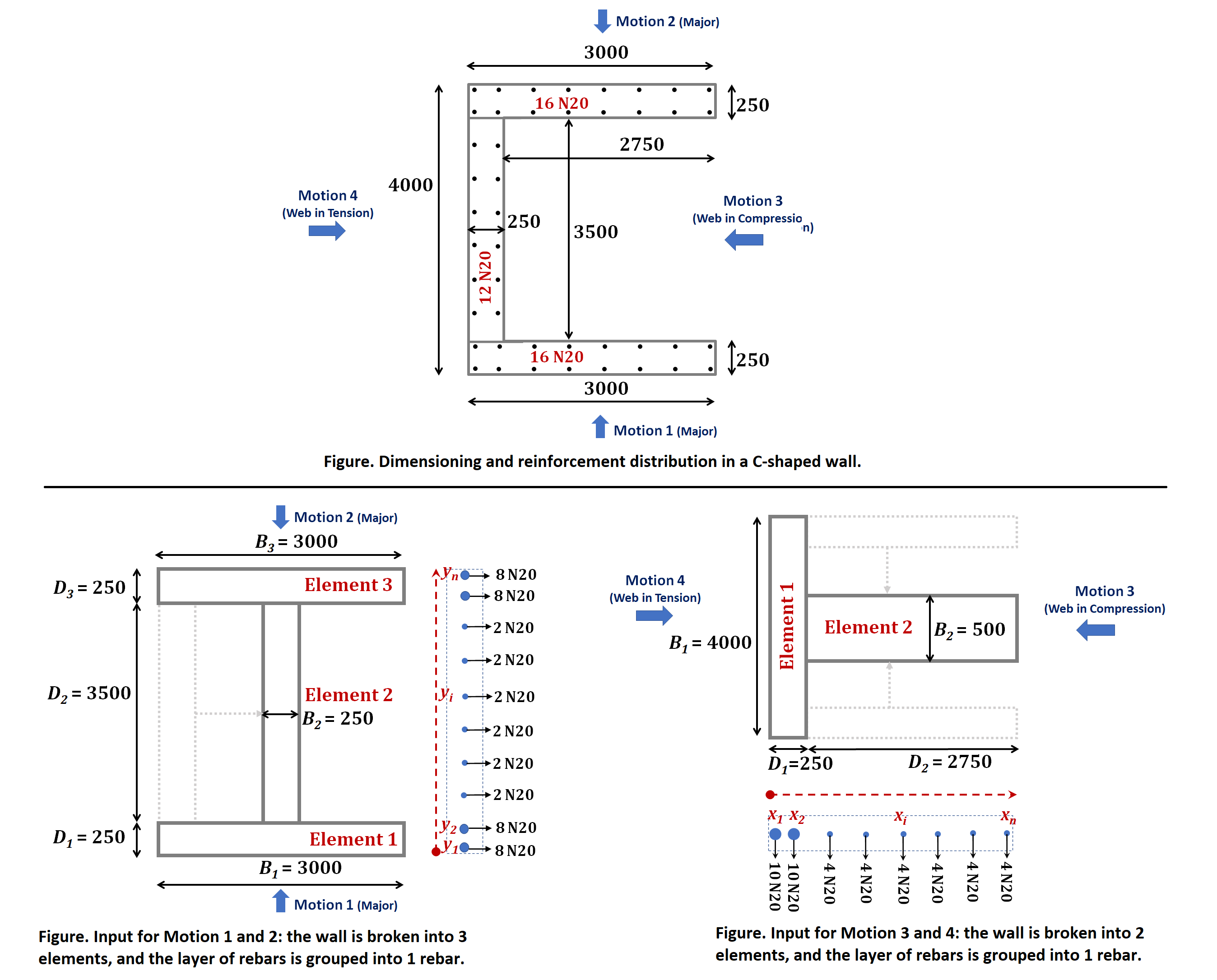
Provide Depth (D) and Width (B) of each elements of the wall starting from either the bottom (for the North-South direction of motion) or the left end of the wall (for the East-West direction of motion) as presented for the example of C-shaped wall.
|
 | |||||||
| C. No. of Layers and Disposition of Vertical Reinforcement: |
| Depth, yi or xi (mm) | Area, Ast (mm2) | |
| 1 | ||
| 2 | ||
| 3 | ||
| 4 | ||
| 5 | ||
| 6 | ||
| 7 | ||
| 8 | ||
| 9 | ||
| 10 | ||
| 11 | ||
| 12 | ||
| 13 | ||
| 14 | ||
| 15 | ||
| 16 | ||
| 17 | ||
| 18 | ||
| 19 | ||
| 20 | ||
| 21 | ||
| 22 | ||
| 23 | ||
| 24 | ||
| 25 | ||
| 26 | ||
| 27 | ||
| 28 | ||
| 29 | ||
| 30 | ||
| 31 | ||
| 32 | ||
| 33 | ||
| 34 | ||
| 35 | ||
| 36 | ||
| 37 | ||
| 38 | ||
| 39 | ||
| 40 |
| D. Other Input Parameters: | |
| I. Concrete Clear Cover, C (mm): | |
| II. Diameter of Vertical Reinforcement, dv (mm): | |
| III. Diameter of Stirrups, ds (mm): | |
| IV. Spacing of Stirrups, Ss (mm): | |
| V. Yield Strength of Vertical Reinforcement, fsy (MPa) : | |
| VI. Ultimate Strength of Vertical Reinforcement, fsu (MPa) : | |
| VII. Characteristics Compressive Stress, f‘c (MPa) : | |
| VIII. Axial load ratio (ALR) or N* (kN) : | |
| IX. Height of the Wall, H (m) : |
| Define Lp in mm: |
| Curvature (1/m) | Moment (kNm) | Force (kN) | Displacement (mm) |
