Seismic Analysis by Generalised Force Method (GFM)
1. Input Parameters:
A. Building’s Floor Plan:
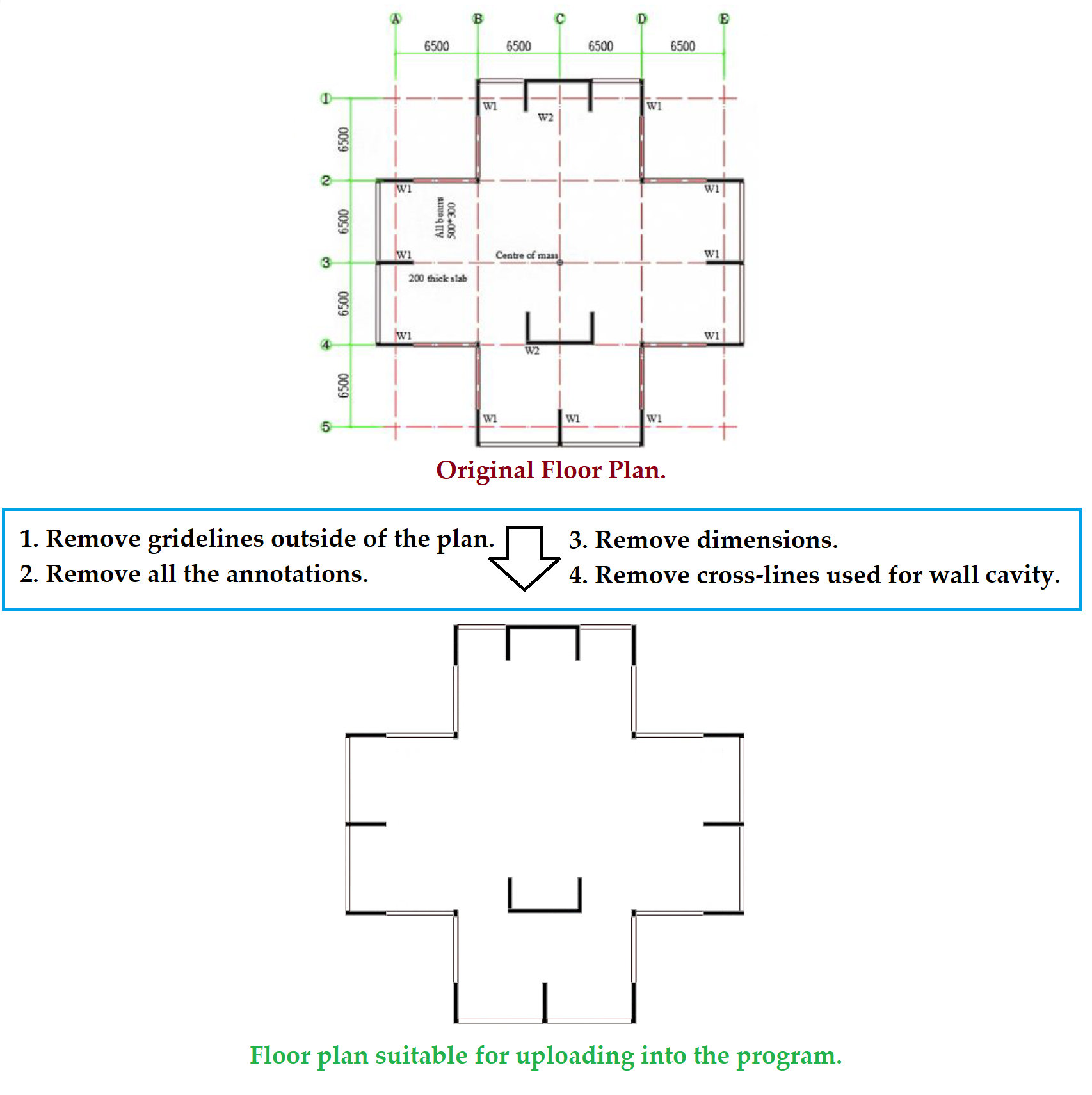
The dymamic analysis is achieved based on the input of the floorplan of the building (drawn to scale). Please upload floor plan (any image file format) below.
Upload Image File of the Building Floor Plan Here:
Note: Any information outside the boundary of the floorplan and any written text within the floorplan need to be removed before uploading the image. Click ‘More Info’ button to see an example.
| Select The Direction of Loading: | |
| Input Length of the Red Rectangle along X-axis (in mm): |
Please verify the dimensions of the structural elements provided in the table below. If the displayed dimensions differ from the actual measurements, kindly update the values by specifying the correct information in the ‘Make Changes’ column.
| Element Description | Current Dimensions in mm | Make Changes in mm |
Select the type of structural system from the following three options:
| Input slab depth (in mm): | |
| Characteristic Compressive Strength of Concrete (MPa): |
| Input Average Length of Beam in the Direction of Loading (in mm): | |
| Input the Cross-sectional Area of Beam (in mm2): |
B. Details of the Building’s Elevation:
| No. of Lumped Masses: |
Note:
- Please provide input for storey mass and height of the roof on the first row and follow the descending pattern up to the base.
- Default floor mass is calculated as: 0.275 tonne x floor area x 3.2 m.
- Default storey height with uniform floor to floor height of 3.2 m is used.
- For user defined mass and height, the table can be filled manually or by performing a copy (CTRL+C) and paste (CTRL+V) of data from an Excel spreadsheet.
| No. | Mass (tonnes) |
Height above Ground (m) |
| 1 (top) | ||
| 2 | ||
| 3 | ||
| 4 | ||
| 5 | ||
| 6 | ||
| 7 | ||
| 8 | ||
| 9 | ||
| 10 | ||
| 11 | ||
| 12 | ||
| 13 | ||
| 14 | ||
| 15 | ||
| 16 | ||
| 17 | ||
| 18 | ||
| 19 | ||
| 20 | ||
| 21 | ||
| 22 | ||
| 23 | ||
| 24 | ||
| 25 |
C. Details of the Seismic Demand:
| Ground Type: | |
| Hazard Design Factor x Probability Factor (kpZ): |
(The input storey mass and storey height above ground are shown in Table 2.)
2. Results:
2.1 Seismic Design Response Spectrum:
Figure 1: Acceleration-Displacement Response Spectrum (ADRS) Diagram
2.2 2D Dynamic Solution Including Higher Modes of Vibration:
The dynamic solution of the seismic response of the building in 2-dimension (no torsion or rotation) is determined as per the following 3 steps.Step 1. Determination of the mode shape (ϕj), participation factor (Γj) and period (Tj) of the first 3 modes of vibration:
The modal solution of the building is determined using the free undamped response of the continuum system (having uniform stiffness along height) represented by the Timoshenko Beam, Eqs. (1-3). $$ {ϕ_{j} = C [cos(x a_{j}) – cosh(x \sqrt{{a_{j}}^2+{P}^2}) – D{sin(x a_{j}) – \frac{a_{j}}{\sqrt{{a_{j}}^2+{P}^2}} sinh(x \sqrt{{a_{j}}^2+{P}^2})}]}\tag{1}$$ $$ {Γ_{j} = \frac{m_{i} ϕ_{j}}{ϕ’_{j} m_{i} ϕ_{j}}}\tag{2}$$ $${T_{j} = \left(\frac{2\pi}{a_{j}b_{j}}\right) \times \sqrt{{\frac{M_{total}H^3}{EI}}}}\tag{3}$$ Where: coefficients C and D, and mode shape parameter (aj) are solved from Eq. (1) using the boundary conditions at the base and roof of the building; P is the stiffness ratio defined as an input; and Mtotal, H, and EI are the total mass, height, and flexural rigidity of the building.
Step 2. Determination of the effective modal mass (Mj) and modal participation ratio (MPRj) $$ {M_{j} = \sum^n_{i=1}({m_{i}}\:{{Γ_{j}}\:\:{ϕ_{i,j}}})}\tag{4}$$ $$ {MPR_{j} = \frac{M_{j}}{M_{total}}}\tag{5}$$ Step 3. Determination of the combined storey and inter-storey drift, storey and base shear, and overturning moment
The combination of storey drift (δi,3 modes), inter-storey drift (θi,3 modes), storey shear (Vi,3 modes), base shear (Vb,3 modes), and total overturning moment (OM) of the first three modes of vibration are calculated using Eqs. (6-11). $$ {δ_{i,3\:modes} = \sqrt{\sum^3_{j}{\left({{Γ_{j}}\:\:{ϕ_{i,j}}\:\:{RSD_{j}}}\right)}^2 }}\tag{6}$$ $$ {θ_{i,3\:modes} = \sqrt{\sum^3_{j}{\left(\frac{{{Γ_{j}}\:\:{(ϕ_{i,j}-ϕ_{i-1,j})}\:\:{RSD_{j}}}}{h_{i}}\right)}^2 }}\tag{7}$$ $$ {F_{i,3\:modes} = \sqrt{\sum^3_{j}{\left({m_{i}:\:{Γ_{j}}\:\:{ϕ_{i,j}}\:\:{RSA_{j}}}\right)}^2 }}\tag{8}$$ $$ {V_{i,3\:modes} = \sqrt{{\left(\sum^n_{i}{m_{i}}\:{{Γ_{1}}\:\:{ϕ_{i,1}}\:\:{RSA_{1}}}\right)}^2 + {\left(\sum^n_{i}{m_{i}}\:{{Γ_{2}}\:\:{ϕ_{i,2}}\:\:{RSA_{2}}}\right)}^2 + {\left(\sum^n_{i}{m_{i}}\:{{Γ_{3}}\:\:{ϕ_{i,3}}\:\:{RSA_{3}}}\right)}^2}}\tag{9}$$ $$ {V_{b,3\:modes} = \sqrt{{\left({V_{b,1}}\right)}^2+{\left({V_{b,2}}\right)}^2+{\left({V_{b,3}}\right)}^2}}\tag{10}$$ $$ {OM = \sum^n_{i=1}({{F_{i,3\:modes}} \times H_{i}})}\tag{11}$$ Where: RSAj and RSDj are the spectral acceleration and displacement of mode ‘j’ at ‘Tj‘, and hi and Hi are the height of each storey ‘i’ and it’s height from the base of the building.
Figure 2: Normalised Mode Shape for the First Three Modes of Vibration
Figure 3: GFM Inter-Storey Drift
Figure 4: GFM Storey Shear
2.4 Solution Including 3D Torsional Amplification:
The floor plan of the building provided as an input is scanned here to determine the position of the centre of mass (CM) and centre of rigidity (CR) and the mass radius of gyration as shown in Figure 5. Then the torsional parameters such as the normalised elastic radius (br) and normalised eccentricity (er) are determined as per [1]. Finally, the 3D/2D displacement ratio is determined as per [2]. The torsional parameters and the 3D displacement profile is plotted against the 2D displacement in Figure 5.Figure 5: Summary of the torsional parameters and the comparison of the 2D and 3D displacement profile.
4. References:
1. Khatiwada, P.; Lumantarna, E. Simplified Method of Determining Torsional Stability of the Multi-Storey Reinforced Concrete Buildings. CivilEng 2021, 2(2), 290-308.
2. Khatiwada, P.; Lumantarna, E.; Lam, N.; Looi, D. Fast Checking of Drift Demand in Multi-Storey Buildings with Asymmetry. Buildings 2021, 11, 13.
3. Standard, A. (2007). AS 1170.4-2007 (Amdt 2018).Structural Design Actions, Part 4: Earthquake Actions in Australia.
Disclaimer
The authors assume no responsibility for any injury, damage, liability, negligence and/or otherwise to any individual or property from the use or application of any of the methods, products, instructions, or ideas contained in the material herein.